


Voice:音読さん
A jig (fixture) is a specialized tool used to clamp and locate a workpiece during machining.Beyond cutting operations, jigs are also widely used in other steps such as assembly.
This page introduces jigs—tools that support the manufacturing process in many ways—and how Yumoto Vietnam applies them in practice.
A jig must be designed to accommodate the tolerance of the part to be machined.A certain clearance between the part and the jig is needed for clamping, but if the clearance is too large the part shifts and accuracy drops.An experienced designer therefore weighs the part's tolerance when choosing the right clearance.
The jig's size must also be considered against the required tolerance.During clamping a jig always has a very slight tilt; the larger the jig, the more the deviation grows at points far from the coordinate origin, and the lower the accuracy.
The tool path must be taken into account during design.In particular, when machining the side faces of a part, the tool may collide with the jig depending on the jig's shape, so this point needs attention.
At Yumoto Vietnam, most jigs are made of aluminum.Aluminum is easy to machine and, being stronger than plastic, holds parts more firmly.

In machining, you must set a coordinate origin for the part.If a part is machined over several processes, every process must use the same origin.For a rectangular part you can use two perpendicular edges to define the X and Y axes and derive the origin; but for a part with a curved shape, the origin is very hard to define this way.
To solve this, Yumoto Vietnam designed and built the jig in Figure 3 to machine curved-shape parts.This jig holds two parts at once—each placed on one of the two central bosses—and uses a corner at the edge of the jig as the coordinate origin.
The jig fixes each part with screws through four holes.This order included several part variants with the same outer shape but slightly different hole positions, so the holes were designed as long slots (oval holes) so that one jig can clamp many part variants.
In addition, because the parts also require side-face machining, the two parts are spaced far enough apart for the tool to pass along the side faces.

To meet recurring orders of several hundred parts at a time, Yumoto Vietnam designed and built a jig for mass production to raise productivity.Previously this order used the jig shown in Figure 4.However, after each part was finished it had to be removed, the screw loosened, and the next part clamped; this repeated manual work took a lot of hand labor and lengthened machining time.
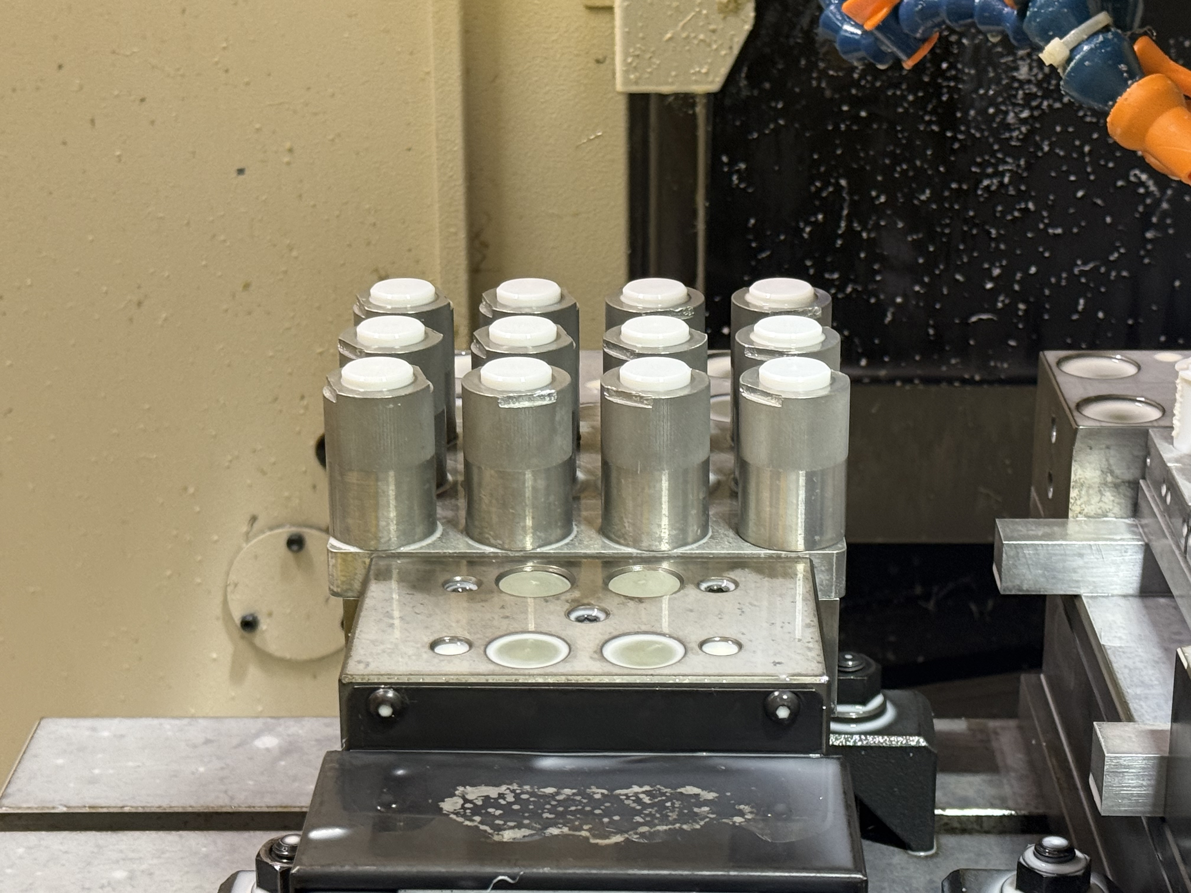
A jig like the one in Figure 5 was therefore designed to machine about 10 parts at once.As a result, the number of manual operations needed for the same quantity of parts dropped to about one-tenth; the machine can keep running through the night after working hours, machine time is used to the fullest, and delivery time is shortened significantly.
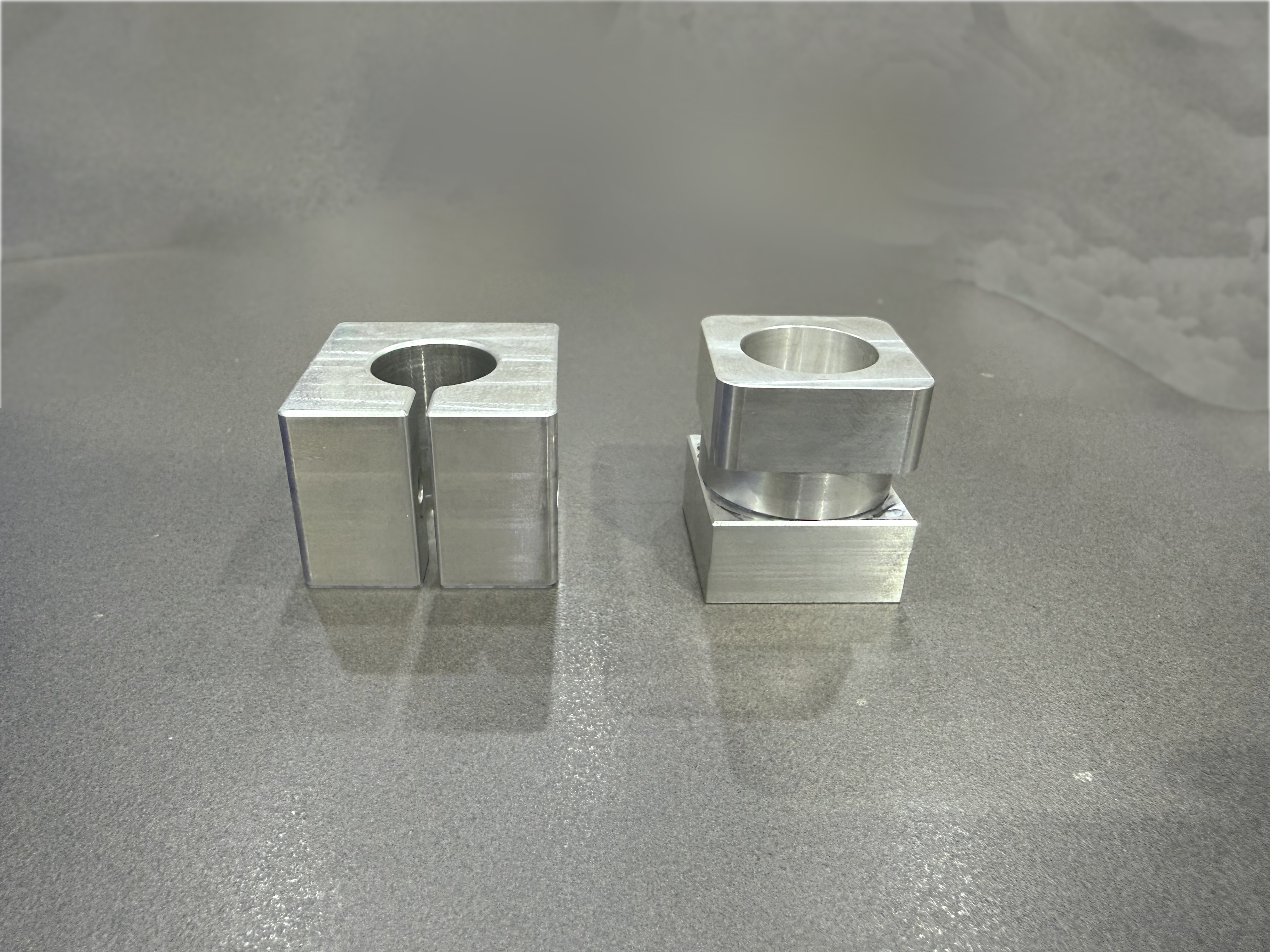

This part is machined in two processes.In Figure 4 and Figure 5, the left jig is for process 1 and the right jig is for process 2.The process-2 jig has tapped threads, as shown in Figure 6 and Figure 7, so it clamps parts faster and more accurately.
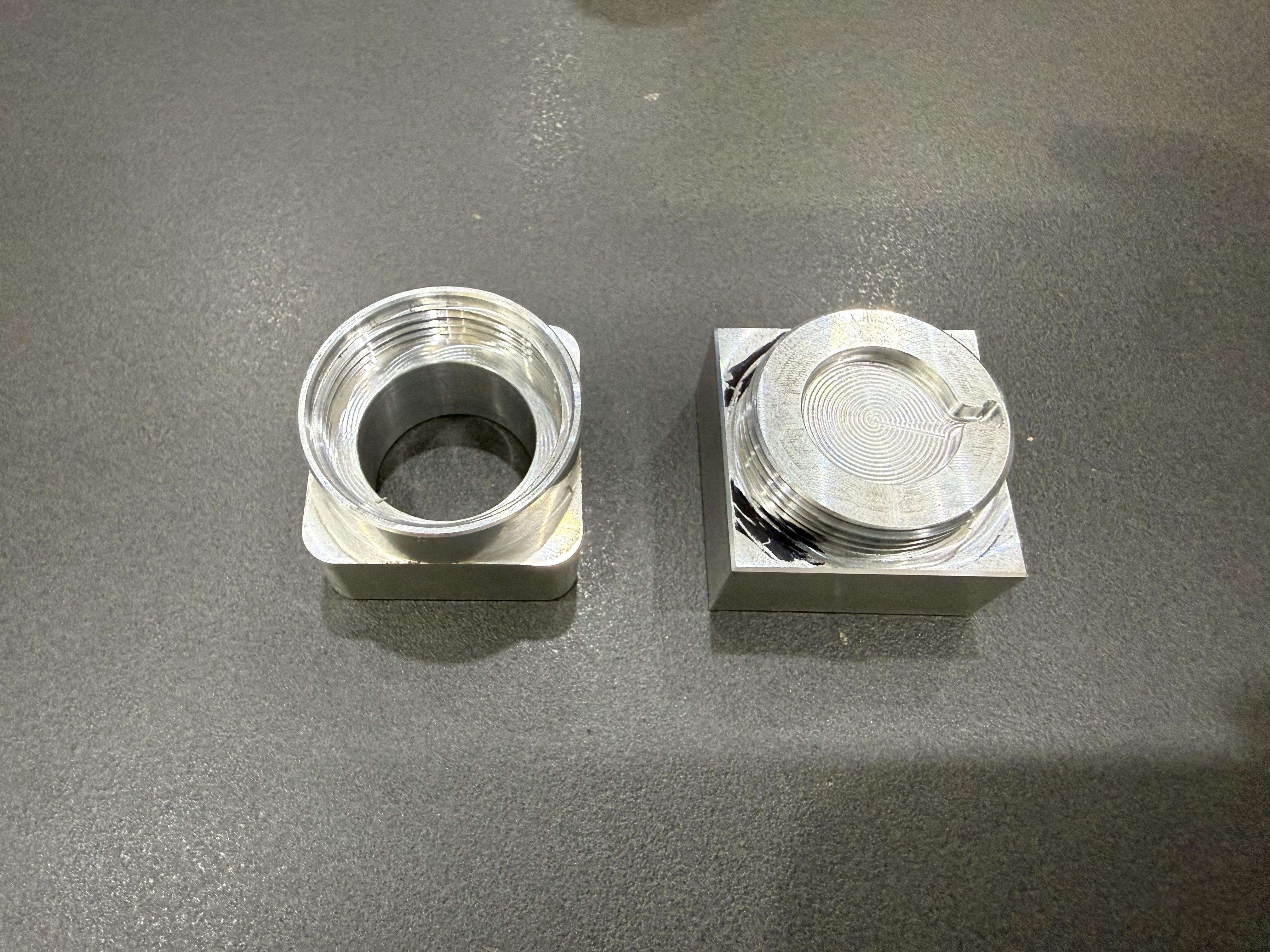

For a round part, the jig must be designed so it can only be clamped the correct way round, as shown in Figure 8.In the jigs of Figure 6 and Figure 7, the boss of the part fits into the jig, so the part cannot be clamped the wrong way.

This part does not require side-face machining, so the parts do not need to be spaced far apart.An oversized jig reduces accuracy at points far from the coordinate origin; therefore the parts are placed close together to machine many at once while keeping the jig as small as possible.
Yumoto Vietnam designs and manufactures jigs for many different production environments, including assembly processes and automation equipment.
If you are considering having a jig made at Yumoto Vietnam, please contact us by email at sales@yumotovn.com.


Copyright ©2023 Yumoto Vietnam Co., Ltd.


